LCD Management

LCD Management

  • Stampa

It easy to see word, phrases, data, etc. on a LCD display

I used a 2x16 display.

The ciscuit diagram for connection to a generic display you can find easly online for example in the tutorial of Arduino as follow.
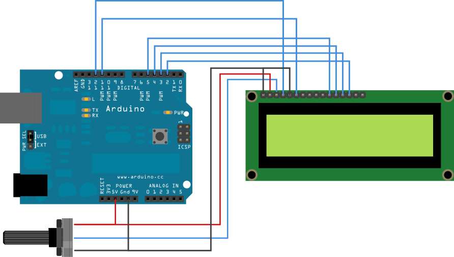
Schema collegamenti

In my case the display is a 1602B

I not know so muth about display, but comparing the connection above with a pattern of display, I don't think you will find difficult to figure out how to connect it. For example the pin D4-D5-D6-D7 in 1602B are corresponding to pins 11-12-13-14, R / W and E respectively 5-6 and so on.

 Then the potentiometer adjusts the contrast of the LCD. A simple trimmer 47k or 100k is good for test operation.

There are two connections A and K (anode and cathode) that are used for display backlighting.

From online examples and with some creativity I implemented this:


#include <LiquidCrystal.h>

LiquidCrystal lcd(7, 6, 5, 4, 3, 2); //define LCD pin
int led = 13,i=2;
unsigned long SendTime = 0;
unsigned long S=0;
bool LED=true;

void setup() {
  lcd.begin(16, 2);
  lcd.print("Hello, World!:-)");
  pinMode(led, OUTPUT); //board led blink
  lcd.setCursor(0, 1);
  lcd.print("T: : :");
}

void blink_led() { //led sub program 
  if (millis() > SendTime + 1000) {
    SendTime = millis();
    if (LED==true) {
      LED=false;
      digitalWrite(led, HIGH);
    }
    else {
      LED=true;
      digitalWrite(led, LOW);
    }
  }
}


void hms() { //convert numerical value time in h m s

              //time sub program

  unsigned long int t=millis()/1000;
  unsigned short int h,m,s;
  if (t >= 3600) { //hour print
    h=millis()/3600000;
    if (h<10) {
      lcd.setCursor(3,1);
      lcd.print(h);
      lcd.setCursor(2,1);
      lcd.print("0");
    }
    else {
      lcd.setCursor(2,1);
      lcd.print(h);
    }
  }
  else {
    h=0;
    lcd.setCursor(2,1);
    lcd.print("00");
  }

  if (t >= 60) { //minutes print
    m=millis()/60000-h*60;
    if (m<10) {
      lcd.setCursor(6,1);
      lcd.print(m);
      lcd.setCursor(5,1);
      lcd.print("0");
    }
    else {
      lcd.setCursor(5,1);
      lcd.print(m);
    }
  }
  else {
    m=0;
    lcd.setCursor(5,1);
    lcd.print("00");
  }


  if (t>0) { //second print
    s=millis()/1000-m*60-h*3600;
    if (s<10) {
      lcd.setCursor(9,1);
      lcd.print(s);
      lcd.setCursor(8,1);
      lcd.print("0");
    }
    else {
      lcd.setCursor(8,1);
      lcd.print(s);
    }
  }
  else {
    s=0;
    lcd.setCursor(8,1);
    lcd.print("00");
  }
}


void point() {  //point sub program
  if (millis()> S + 249) {
    S = millis();
    if (i>4) 
      i=1;
      lcd.setCursor(10+i,1); // lcd.setCursor(17-i,1); reverse point
      lcd.print(" ");
    }
    lcd.setCursor(11+i,1); // lcd.setCursor(16-i,1);
    lcd.print(".");
    lcd.setCursor(10+i,1); // lcd.setCursor(17-i,1);
    lcd.print(" ");
    i++;
  }
}

void loop() { //main program

  point();  //sub program call
  blink_led(); 
  hms();

}

From the program comments, you shuld understand how it works.

Now you can make changes to get familiar and  have fun with sperimentation.

Some photos of the construction:


Now a short video done long ago before changing the bad connections with the best:

VIDEO